I realized as I was going back through the sections and double checking their work that they didn’t do two things. One was install the front floor boards permanently and two was to secure the rear vents. I got both of those done today though it took quite a bit of time just because of how many rivets there were and the angles that they were at. Good to have it done and secure now!
I decided to move forward with some of the sections that I knew needed to be done and would not interfere with the other sections I was jumping past. So I decided to do the brake lines. A pretty easy section in terms of how much time that was needed to complete it. The only discrepancy I found was that on the rubber mounts that isolate the brake lines from the airframe stated I was to use 8 of the clamps and then 8 AN515-8R8 screws. But I only have 7 holes to screw into because the firewall mount was to be shared between the two clamps up there. Also, come to realize, the nutplate on the firewall is meant for an 10/32 thread not an 8/32 which is what the manual stated. So I’m going to have to see what the equivalent is for an AN515-8 and I need it to be longer too as the 8 size was too short. I need it to be a 10 size or 12. Either way, I bet you someone in the forums has had the same issue so I’ll take a look at what they did. Here are pictures of the work from tonight.
I also printed more of the avionics that I’ll be using. I have quite a few to go still.
Last night before I went to bed I decided I needed to 3d print the components I was going to be installing in my system so I could plan space, cable runs, etc. And below is the fruit of my efforts (granted Garmin provided the models)
The first one is the Garmin GSU 25C ADAHARS unit. This will take my pitot static system and also it’s installed plane to give me my speed, altitude, AOA, and attitude. This combined with the magnetometer give me the entire picture of where the plane is oriented and at what speed. The second unit is the Garmin GAD 27 which allows me to interact with the lights, flaps, trim, etc. I won’t be using it for the trim as I will be connecting the trim motors up to the Garmin autopilot servos, but I will use it for the lights, flaps, and interior lights so far. There are other features that I’m determining how I will use them, etc.
I then spent quite a bit of time working out my primary electrical system. I will need to buy some firewall penetration posts that will allow me to pass the heavy gauge wire through more easily without the worry of it chaffing. These posts will allow me to attach the lugs to them and secure the connections as needed. There are other components that I need to discover too as I saw on quite a few installations that they had a grounding bus bar with quite a few components terminated to it. I’m not sure how many I will need but I’m going to guess there are quite a few sensors that need power that I can put there. I need to dig into this and what the Lycoming engine and Garmin GEA 24B will need to monitor the IO-540 properly.
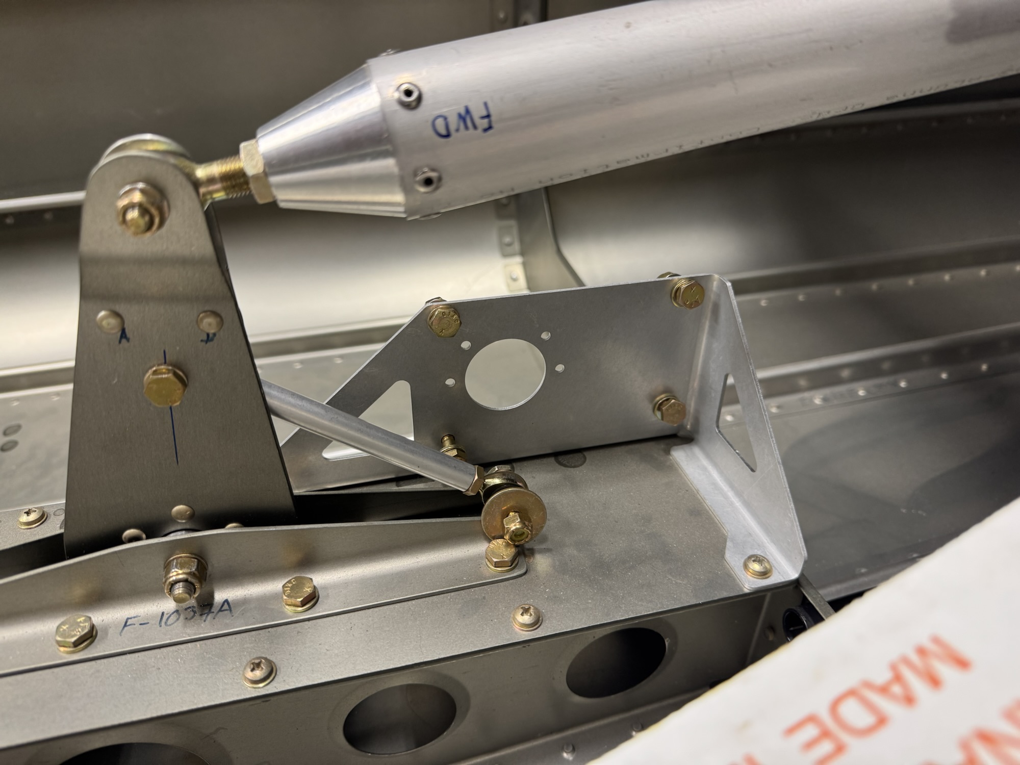
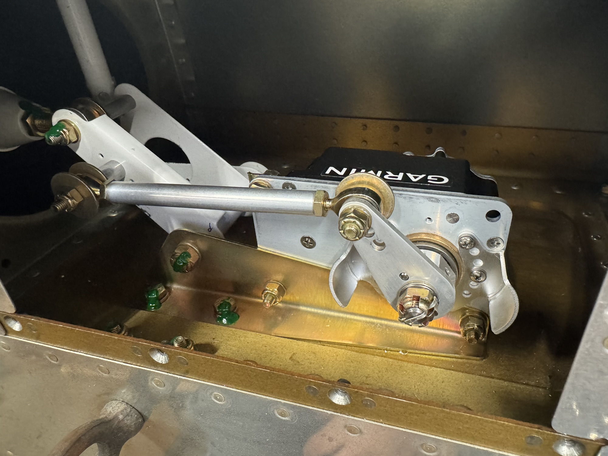
I also got a TON of hardware sorted out and I would have finished the job but I ran out of labels to print on. So while I ordered and wait on that, I decided to finish the Garmin yaw servo mount install. I got the four rivets drilled out and installed the bracket without too much hassle.
I spent a good portion of my build time today working on the avionics and power distribution documentation. I decided I’m going to swap out the GTR 205xR remote comm radio for an actual nav/comm radio. This will be my separate backup for IFR navigation just in case the GTN 750Xi konks out on me. This will take only a slight modification to the wiring but it will take a bit more panel space so I’m going to have to figure out what space I have for it. I’m working on 3d printing some components so that I can move them around and see how big they will actually be in the panel and where I need to mount them both as well as the LRUs that will be behind the panel and where those should be mounted. Below is the documentation I have now. I was going one way with it but then I ran out of space so I’m going another way. That’s why it looks so chaotic right now.
I also mounted the Garmin pitch servo mount and then realized when I went to mount the Garmin yaw servo mount, I will have to remove it again to mount that bracket LOL I swear I should read all of it at once as I knew they were very close to each other. Oh well, not a huge ordeal to remove it. I do need to remove some rivets from the bulkheads in that section as the yaw bracket uses those same holes for its lower supports. That will be fun as they are further back so I will have to lay inside the tailcone for that.
And finally I mounted the cabin heat inlets to the firewall. It was a step they didn’t do as part of the quick build in section 28 so I went ahead and got that mounted. I will have to go back and put some proseal around all as they suggested.
Oh, I almost forgot! I mounted the magnetometer. I found also in section 48 page 10 that the door sill is considered flat and level for the airplane which the leading and trailing edge of the wing create a line that parallels that. So I used that method to get the level flight attitude of the wing for mounting the magnetometer within 3 degrees of level.
I need to plan the conduits that will traverse the rear seat and baggage area. There isn’t any good way to access that area after I seal it off so I need to get conduit run through that area so I can make runs down the road. In the mean time, I decided to start terminating the wiring in the wings and in the fuselage that I already had planned. I got the pitch trim servo terminated first. The pinout was 1 – White, 2 – Grey, 3 – Orange, 4 – Blue, 5 – Green
I then decided to install the Garmin servo that way I can get the CANBUS wiring going to it and down to the magnetometer.
I then started looking at where to install the magnetometer on the wing tip and one of the criteria is that is must be within 3 degrees of level flight. As such I think I need to do some research to see what level flight is for this wing chord and shape before I just go drilling holes. I think putting it further back on the wing will be best so that I can stay away from the high powered landing and taxi lights.
Finally, since I still had some time in the night I decided to terminate the rear lights for the wing tips. I will need to then terminate the wiring in the wing for the wing tip and add 5 wires that are spliced into the right wires on the main harness to power the rear wingtip lights. I also need to glue in some zip tie mounts in the wing tip so that I can control the wires and they don’t bounce around. I also think I’m going to add some chaffing conduit to the wires going to the rear lights so that they are bundled more easily and saved from any possible chaffing. Plus they’ll just look nicer and more professional. The pinout for the rear light was 1 – Red, 2 – Black, 3 – Blue, 4 – Yellow, 5 – Green
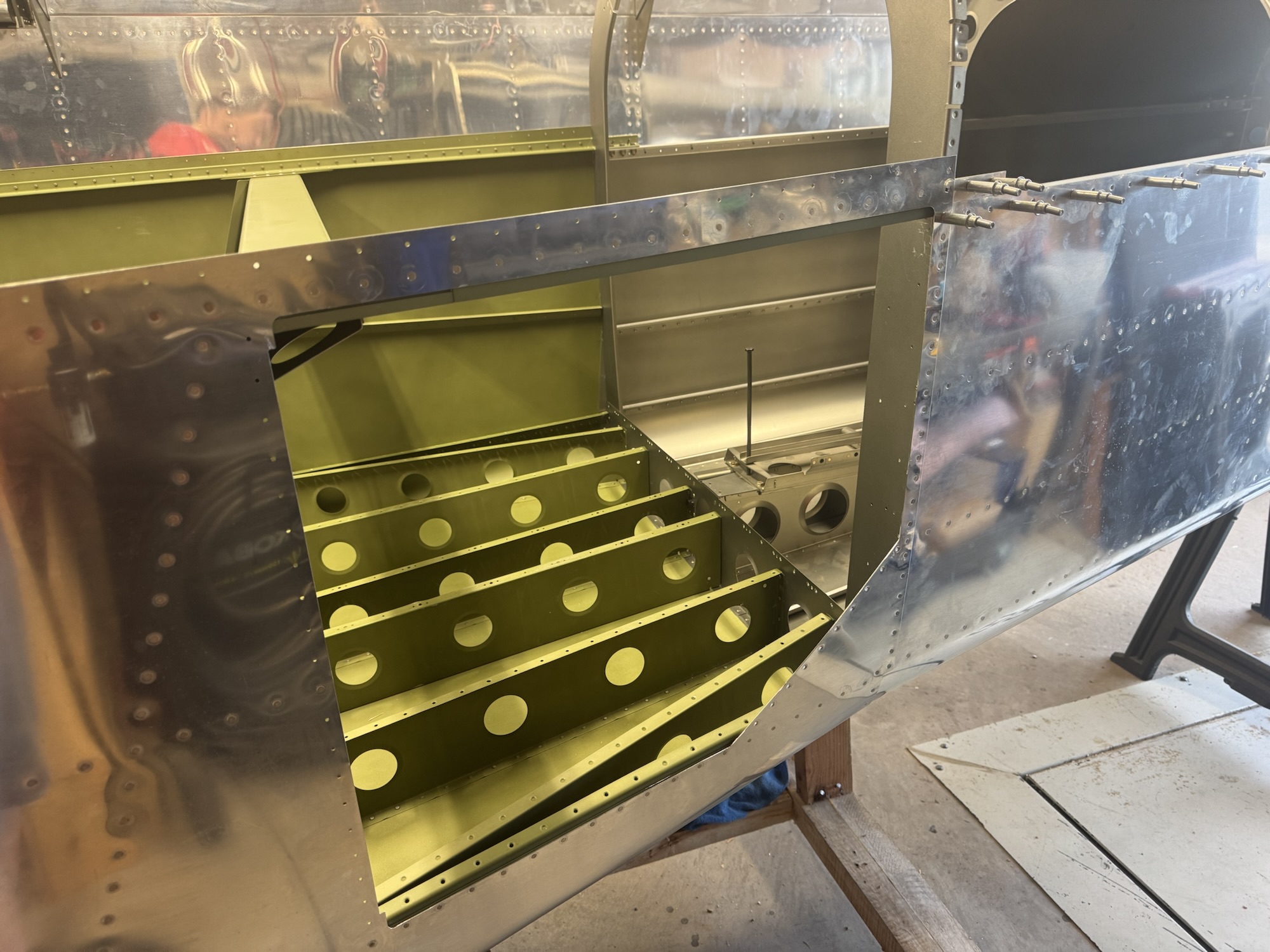
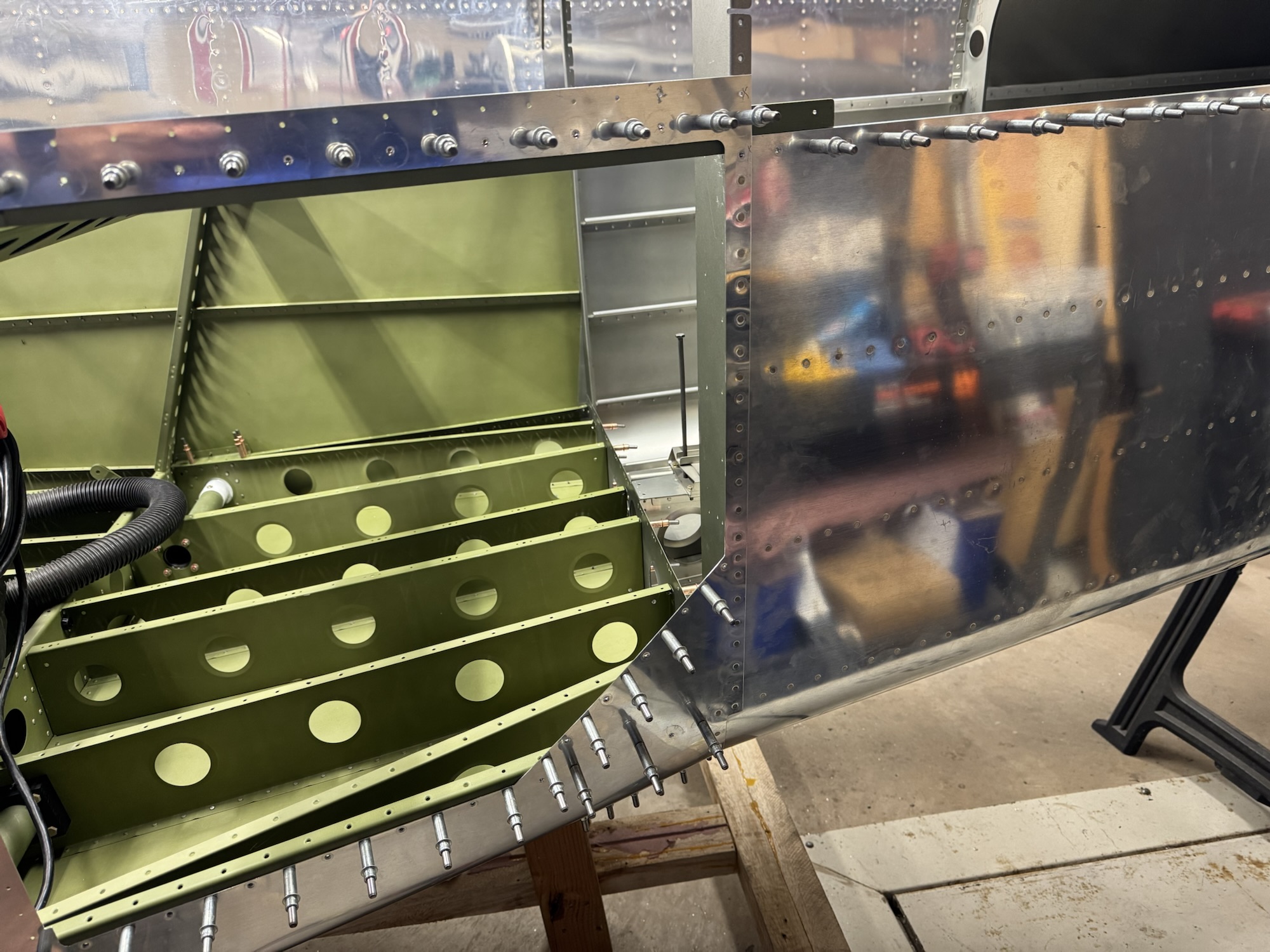
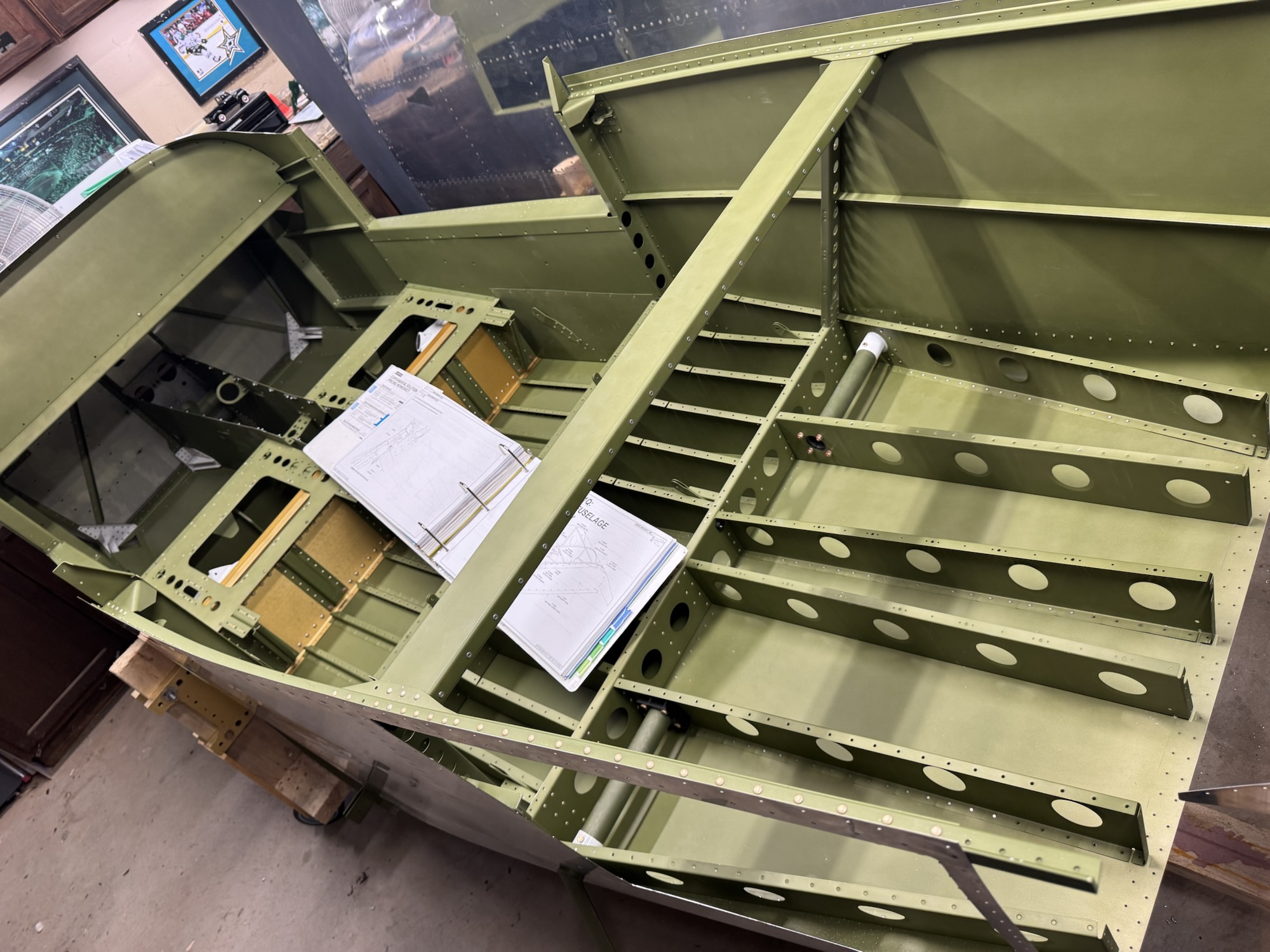
I finished the empennage today with some help from Brendon and Kate. Trying to work on the ground while also having to be in the fuselage was not going to work with just one person. But all of the rivets have been set. I am surprised that they didn’t install these edges that attach to the skin that the baggage floor rests on. They didn’t need to be off for the empennage to be set and it even has them install it in earlier sections. Either way I went back and installed those along with the shims that go with the baggage door opening side. I guess they wanted more strength there since that is where luggage will be entering. Either way it looks good and is ready for the next step! I need to see what parts are needed as I left some parts in storage so I might need to bring some of those back soon.
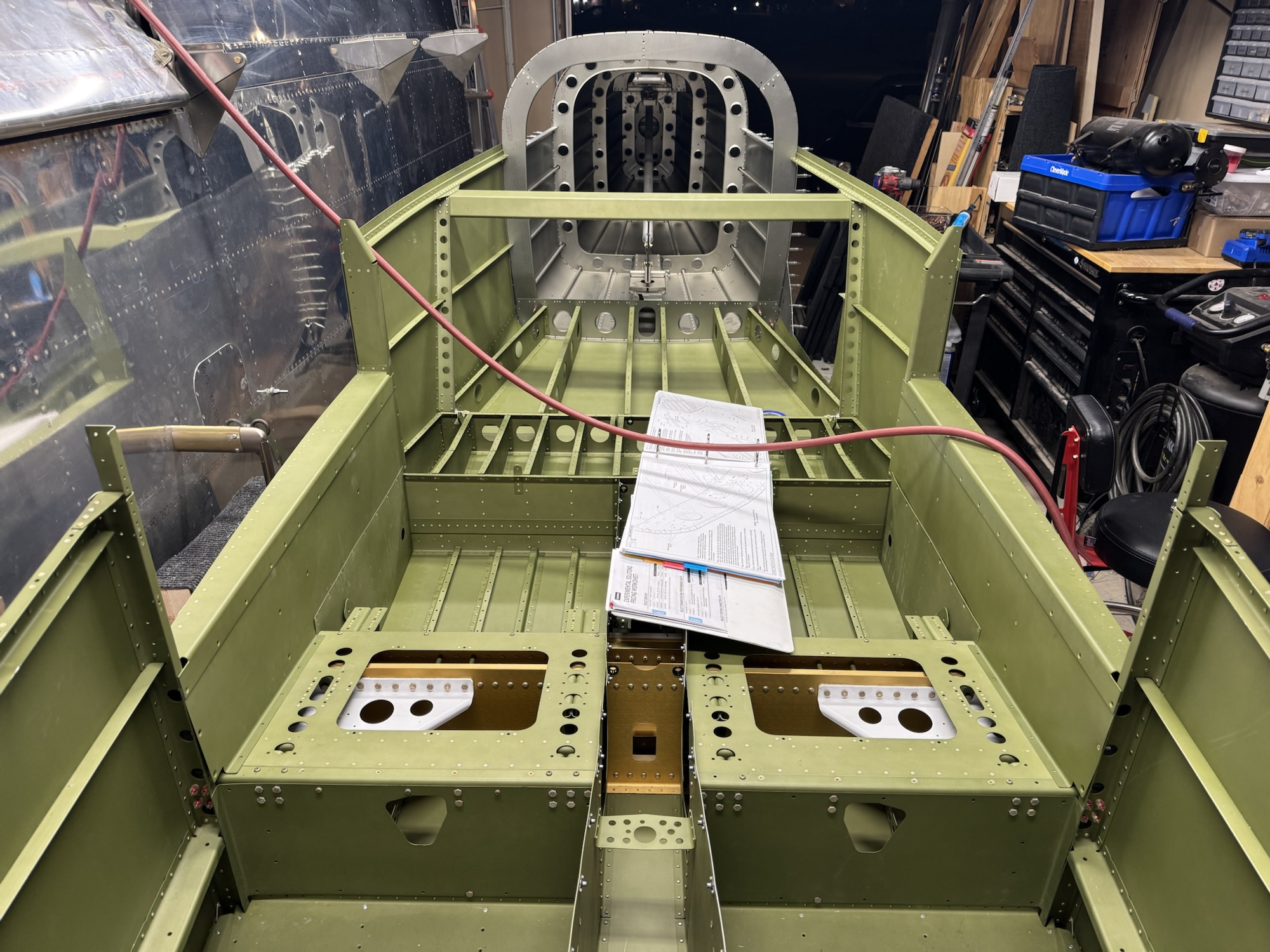
Lots of work that is hard to show in this picture, but I got everything match drilled, deburred, and dimpled. I then got the tailcone back on. I ended up having an easier time doing it myself by putting the tailcone on a single saw horse but almost perfectly balanced but a little heavier towards the fuselage. That allowed me to work each side in much easier. I got everything reassembled like the picture from yesterday and I got one side of the riveting done along the F-1006 bulkhead. Tomorrow I hope to finish all of the riveting but we’ll see. I need to work on my boys’ car as it has had a transmission leak for quite a while and I’m done with the fluid stain on the driveway and I want to fix the leak first before I use the cleaner. I suspect the drive shaft seals from when I swapped the engines out and I might have messed them up when inserting the drive shafts.
I didn’t get a ton of time today to work, but I did get all of the mating surfaces inside the plane match drilled. I got the shims fabricated for the trailing end of the top longeron to skin so there’s identical thickness of skin and no odd pillowing of the skin when I rivet it. I got the top skin mounted so that I can match drill the external skins tomorrow. Once that is done I’ll have to pull this apart to deburr and dimple and then reassemble it for the last time to rivet it together.
I got all of the bulkheads drilled and dimpled. The rest of the night was mating up the empennage. The left longeron was a bit long with what they had from the factory on the fuselage. The longeron that was on the empennage was just the right length with the edge distances that were required for the rivets. So it took alot of time filing the longeron on the fuselage down but I finally got it at the right depth. It is definitely alot of work to get everything to fit together but it fits. I will start match drilling the holes tomorrow after I verify that everything lines up and after I get back from helping someone pickup a food order from the Bishop’s storehouse.
Oh I almost forgot. I also removed the upper forward fuselage that they had temporarily pop riveted into place. That didn’t take too long though.
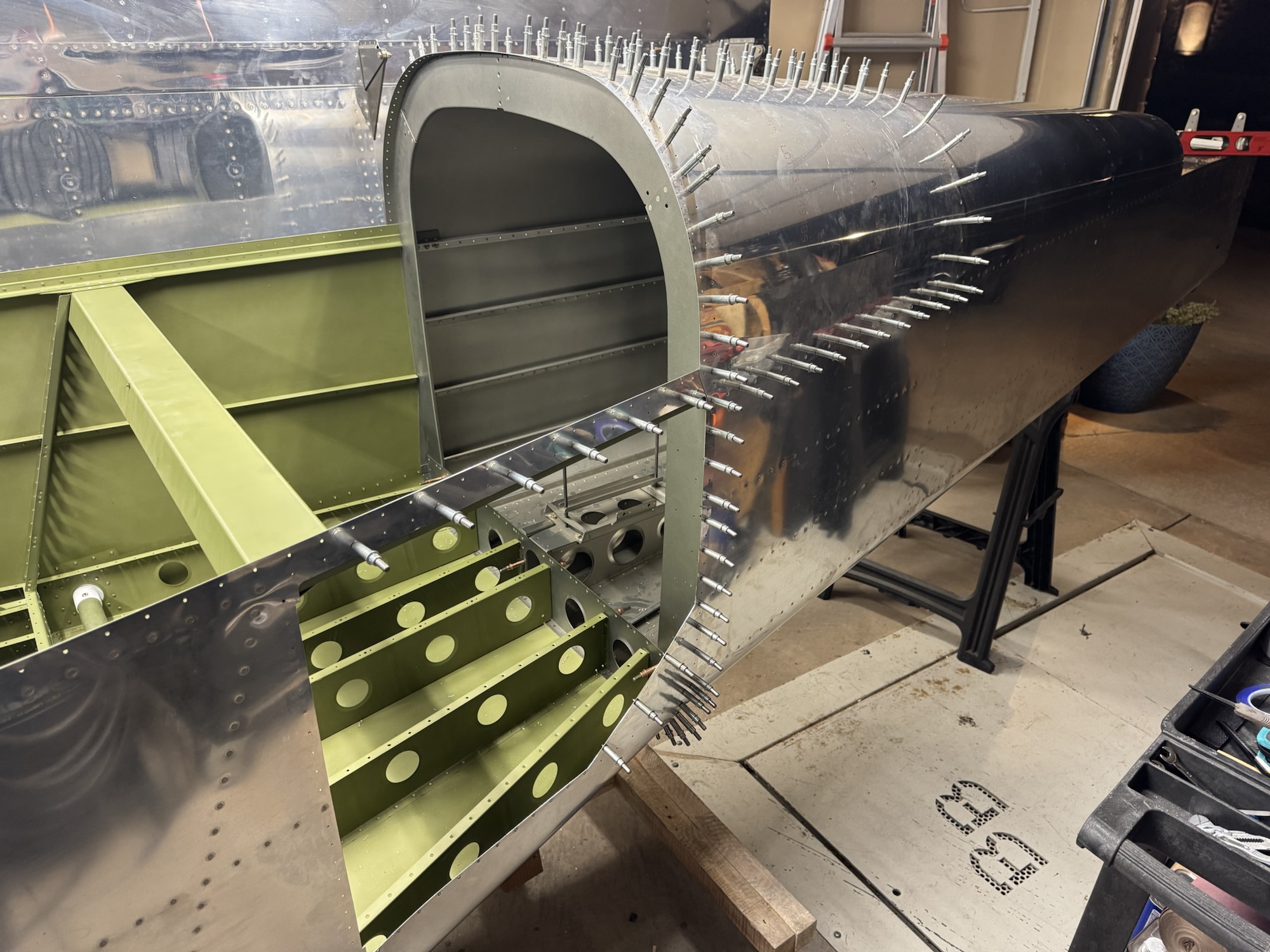
Tonight was the first real night of fuselage work. I had to remove the pop rivets they installed to hold down the components that they did not perform the final install on. I then inspected their work which was really good! They did an excellent job with all of their rivets, fabrication, and primer work. I got the rear steps installed and I removed the baggage door and started deburring it all. I also got some time today to start my wiring diagrams. The block diagram appears complete so I started reviewing the documentation so that I could get the connector pin outs documented for what I will be using.