I am so bad about remembering to take pictures while I am working. Either way, I got the wiring in that I needed that is the correct gauge for the power and ground on the GSA 28. I got that run along with a wire for the CWS/Disconnect, terminated it all and got it hooked up to the GSA. I grounded the GSA to the wing rib next to it that was away from all of the aileron actuation. I just need to finish the wingtip lighting in the left wing and the wings will be done entirely.
On top of that, Andrew and I went and got the canopy out of storage and uncrated it. It will be ready when I get back from DC here in a week and a half, so the project will sit for a bit while we go to the band competition and then my training trip.
I wrapped up the CANBUS wiring and the rest of the harness for the GMU 11 magnetometer. I then remounted the wing tip and finished the CANBUS wiring at the roll servo. The larger wire gauge for the servo should be here sometime this week which will allow me to finish up the cabling to the servo.
I got the CANBUS wire run for the right wing. I also got the power run for the GMU and the GSA but I decided I’m going to up the wire size for the GSA from 22ga to 20ga due to the 2.8 amps it could pull and the distance I’m running. I just feel more comfortable having that gauge so it isn’t so close to the limits of the wire. I’ll have to wait for that to come in. I also am going to have to research how to terminate this CANBUS wire as it isn’t the same wire we used in the class. He said we should use the CANBUS specific wire for our long runs but that it was okay to use the mil-spec wire for the shorter runs in the panel, etc. Well the construction of the shielding is way different so I’ll more than likely need to get solder sleeves which I don’t have any right now.
I decided to finish up the wiring for the wing tip. I need to double check some things now because when I looked at the diagram it looked like some of them they needed as local grounds but the FAQ states that everything should be run back to a central ground to avoid any noise in the audio system. I shouldn’t have let so much time pass between starting this and completing it, but if I need to correct something I can still do it.
I decided to go ahead and get the ELT installed since I have all of that ready to go. It went well up until I started pulling the rivets at the top. The first one got stuck in my rivet gun. This thing is pictured above the place it went; in the TRASH! This is the last time I buy Arrow products as I’ve had nothing but problems with them either from my staple guns or now this rivet gun. I’ll have to see if I can find one tomorrow that’s from a brand name I can trust that still has a small enough head on it to reach in tight areas. That’s the whole reason I bought this one was because the head was pretty small. Either way, I got the bottom four rivets pulled and I just need to pull the top rivets so for all intents and purposes this ELT is installed as it won’t take me more than 5 minutes to pull those top rivets.
Last night before I went to bed I decided I needed to 3d print the components I was going to be installing in my system so I could plan space, cable runs, etc. And below is the fruit of my efforts (granted Garmin provided the models)
The first one is the Garmin GSU 25C ADAHARS unit. This will take my pitot static system and also it’s installed plane to give me my speed, altitude, AOA, and attitude. This combined with the magnetometer give me the entire picture of where the plane is oriented and at what speed. The second unit is the Garmin GAD 27 which allows me to interact with the lights, flaps, trim, etc. I won’t be using it for the trim as I will be connecting the trim motors up to the Garmin autopilot servos, but I will use it for the lights, flaps, and interior lights so far. There are other features that I’m determining how I will use them, etc.
I then spent quite a bit of time working out my primary electrical system. I will need to buy some firewall penetration posts that will allow me to pass the heavy gauge wire through more easily without the worry of it chaffing. These posts will allow me to attach the lugs to them and secure the connections as needed. There are other components that I need to discover too as I saw on quite a few installations that they had a grounding bus bar with quite a few components terminated to it. I’m not sure how many I will need but I’m going to guess there are quite a few sensors that need power that I can put there. I need to dig into this and what the Lycoming engine and Garmin GEA 24B will need to monitor the IO-540 properly.
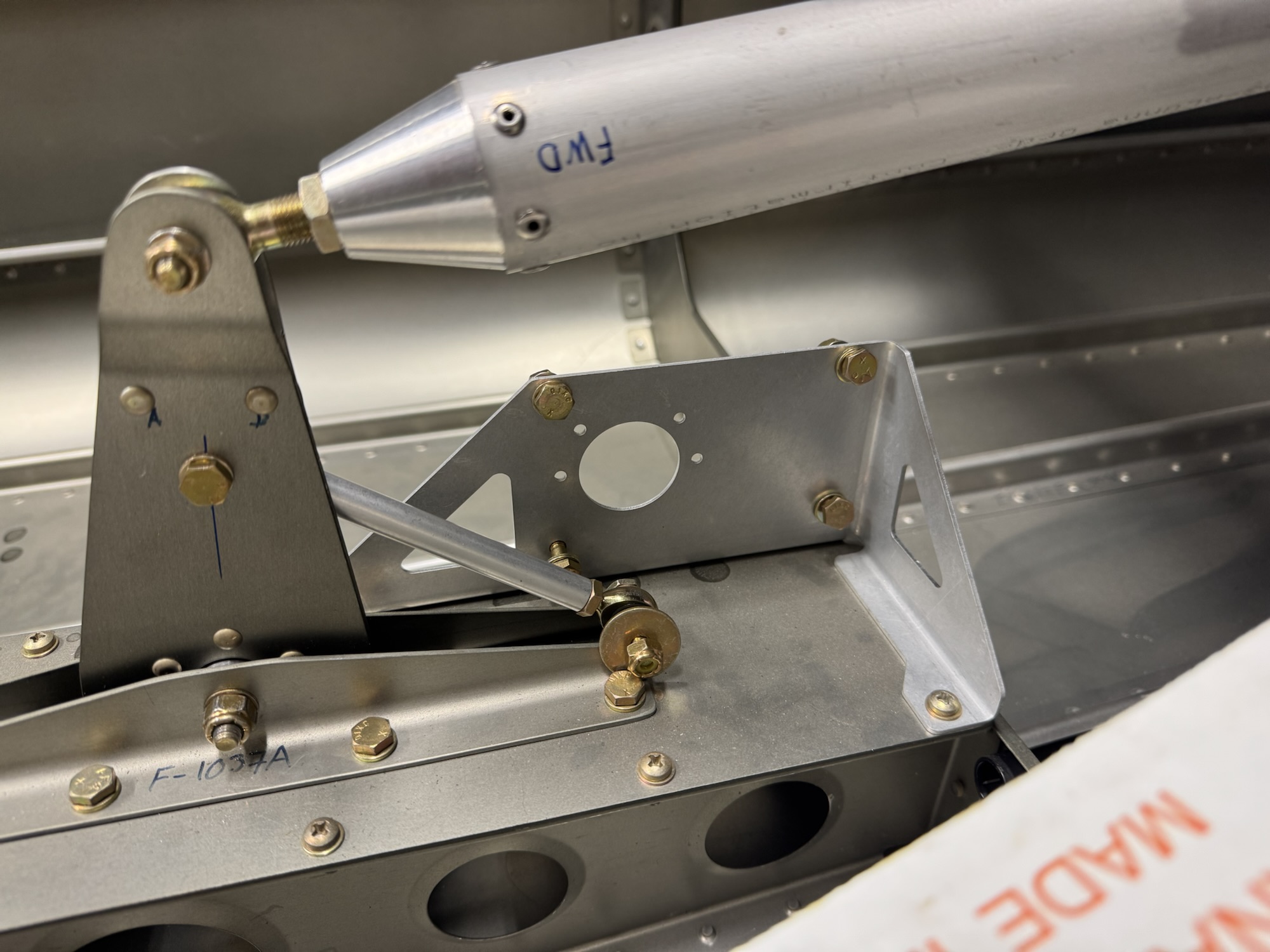
I also got a TON of hardware sorted out and I would have finished the job but I ran out of labels to print on. So while I ordered and wait on that, I decided to finish the Garmin yaw servo mount install. I got the four rivets drilled out and installed the bracket without too much hassle.
I spent a good portion of my build time today working on the avionics and power distribution documentation. I decided I’m going to swap out the GTR 205xR remote comm radio for an actual nav/comm radio. This will be my separate backup for IFR navigation just in case the GTN 750Xi konks out on me. This will take only a slight modification to the wiring but it will take a bit more panel space so I’m going to have to figure out what space I have for it. I’m working on 3d printing some components so that I can move them around and see how big they will actually be in the panel and where I need to mount them both as well as the LRUs that will be behind the panel and where those should be mounted. Below is the documentation I have now. I was going one way with it but then I ran out of space so I’m going another way. That’s why it looks so chaotic right now.
I also mounted the Garmin pitch servo mount and then realized when I went to mount the Garmin yaw servo mount, I will have to remove it again to mount that bracket LOL I swear I should read all of it at once as I knew they were very close to each other. Oh well, not a huge ordeal to remove it. I do need to remove some rivets from the bulkheads in that section as the yaw bracket uses those same holes for its lower supports. That will be fun as they are further back so I will have to lay inside the tailcone for that.
And finally I mounted the cabin heat inlets to the firewall. It was a step they didn’t do as part of the quick build in section 28 so I went ahead and got that mounted. I will have to go back and put some proseal around all as they suggested.
Oh, I almost forgot! I mounted the magnetometer. I found also in section 48 page 10 that the door sill is considered flat and level for the airplane which the leading and trailing edge of the wing create a line that parallels that. So I used that method to get the level flight attitude of the wing for mounting the magnetometer within 3 degrees of level.
I need to plan the conduits that will traverse the rear seat and baggage area. There isn’t any good way to access that area after I seal it off so I need to get conduit run through that area so I can make runs down the road. In the mean time, I decided to start terminating the wiring in the wings and in the fuselage that I already had planned. I got the pitch trim servo terminated first. The pinout was 1 – White, 2 – Grey, 3 – Orange, 4 – Blue, 5 – Green
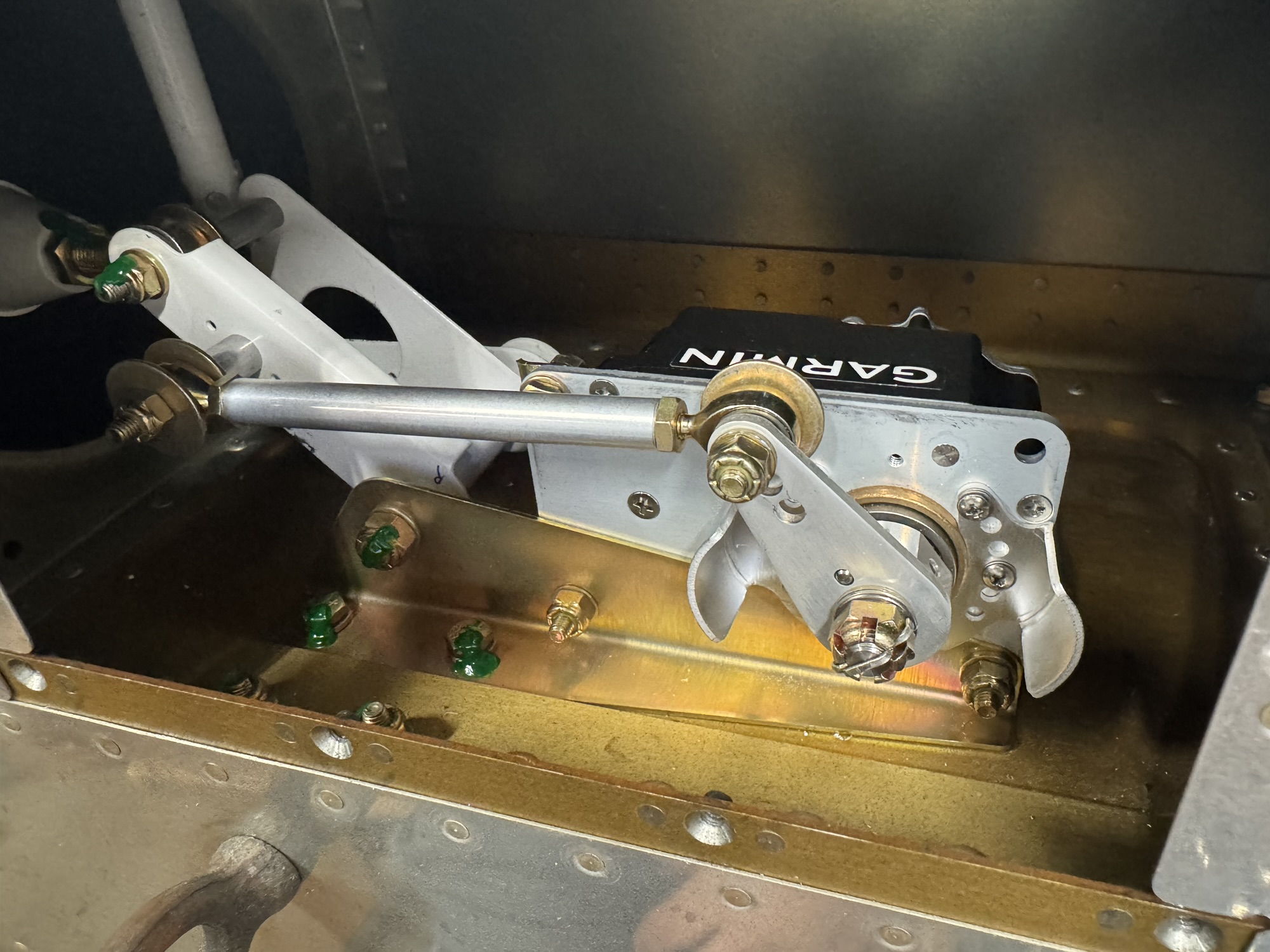
I then decided to install the Garmin servo that way I can get the CANBUS wiring going to it and down to the magnetometer.
I then started looking at where to install the magnetometer on the wing tip and one of the criteria is that is must be within 3 degrees of level flight. As such I think I need to do some research to see what level flight is for this wing chord and shape before I just go drilling holes. I think putting it further back on the wing will be best so that I can stay away from the high powered landing and taxi lights.
Finally, since I still had some time in the night I decided to terminate the rear lights for the wing tips. I will need to then terminate the wiring in the wing for the wing tip and add 5 wires that are spliced into the right wires on the main harness to power the rear wingtip lights. I also need to glue in some zip tie mounts in the wing tip so that I can control the wires and they don’t bounce around. I also think I’m going to add some chaffing conduit to the wires going to the rear lights so that they are bundled more easily and saved from any possible chaffing. Plus they’ll just look nicer and more professional. The pinout for the rear light was 1 – Red, 2 – Black, 3 – Blue, 4 – Yellow, 5 – Green